
A rebuilt board is only proven when it passes inspection and functional test. AOI, X-ray, flying-probe and functional test verify that the reverse-engineered PCBA matches the original electrically and mechanically before it ships back into service.
The question every rebuilt board must answer
Every reverse engineering project ends the same way: a new board, physically faithful to the original, assembled from a reconstructed schematic and BOM. And every customer asks the same quiet question before installing it into equipment worth ten or a hundred times the board's value: will it actually work?
That question is fair, because the failure mode of a rebuild isn't obvious. A board with a reconstruction error doesn't look defective. It solders perfectly, powers up cleanly in the easy cases — and then shorts two nets the first time a specific relay switches, or misreads a sensor at temperature extremes. The defect was introduced silently, pages ago in the reconstruction, and only disciplined testing finds it.
That's why we treat testing not as the end of a reverse engineering project but as the proof step of the reverse engineering itself — the fifth of the five steps described in our reverse engineering walkthrough.
Why testing a recovered design is different
Testing a normal production board is well-trodden: there's a golden sample, a test spec from the original design phase, known-good units to compare against. A reverse-engineered board has none of that:
- No golden sample — or rather, the golden sample is the aging original, which may itself drift.
- No original test spec — what the OEM tested at end-of-line is usually unknown.
- Reconstruction uncertainty — the design data is recovered, not authored, and every recovery step can introduce error.
- Substituted components — modern replacements for EOL parts bring subtle differences that only appear under test.
Standard workmanship testing covers the assembly. The additional job — verifying the reconstruction — is what separates serious RE verification from a board that merely resembles its ancestor.
The layered test strategy for reverse-engineered PCBA
Our PCBA testing workflow layers methods so each catches what the previous can't:
| Layer | What it checks | What it catches on a rebuild |
|---|---|---|
| AOI | Solder joints, placement, polarity | Assembly defects introduced by the new build |
| X-ray inspection | Hidden joints — BGA, QFN, shielded parts | Voids and cold joints invisible from the surface |
| Electrical test (flying probe / ICT) | Opens, shorts, basic component values | Reconstruction errors — the rebuild's connectivity vs. the recovered netlist |
| Functional test | The board doing its actual job | Behavioral differences from substituted parts or inferred circuit regions |
| First-article inspection | Documentation of the build | Baseline evidence before any volume is produced |
The test that matters most: proving the netlist
Here is the step unique to reverse engineering. Flying probe test moves needles across the board to measure connectivity — opens, shorts, and basic component presence — without building a custom fixture. On a normal product it's a manufacturing check. On a rebuild, it's something more: the probe program can be generated directly from the reconstructed netlist, so the physical board is audited against the recovered design node by node.
If a via was misread during layer extraction, or a net was merged with its neighbor during schematic reconstruction, the flying probe finds it — before power is ever applied. No other test stage does this. Skipping it means the first functional test of the reconstruction is the moment the customer powers the board in their machine.
Functional test: rebuilding the spec that didn't survive
When no original test spec exists, the spec is rebuilt from the board's job. What power rails should come up, in what order? What signals should appear on the interface connectors, at what timing? What does the board do when the machine commands it to do the one thing it exists to do?
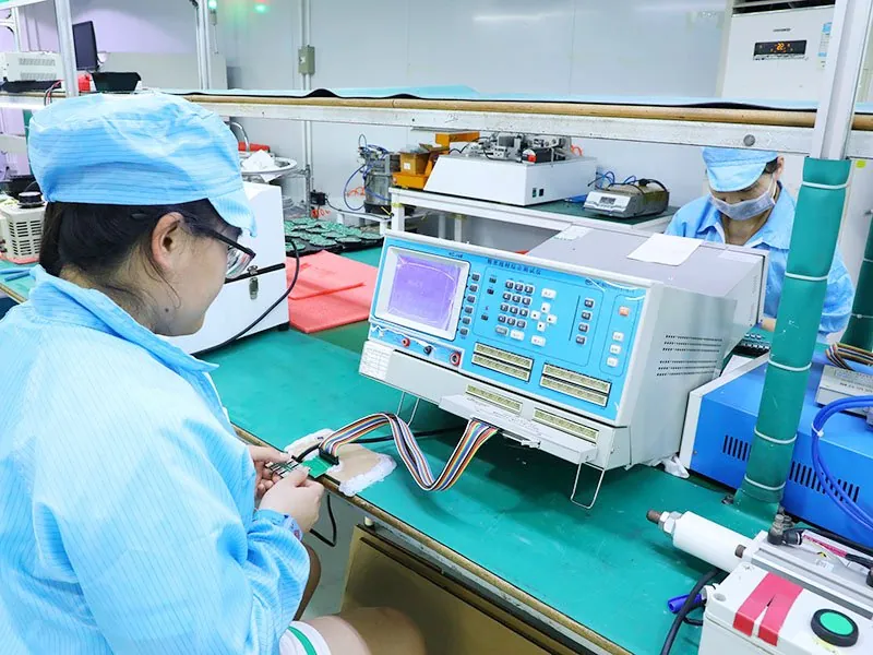
The strongest form of functional verification is comparative and contextual: run the rebuilt board and the original side by side, and where possible, install the rebuild in the actual equipment it will serve. A control board that passes a bench test can still misbehave on a factory floor with real loads, real cable lengths, real electrical noise. Testing in situ closes that gap.
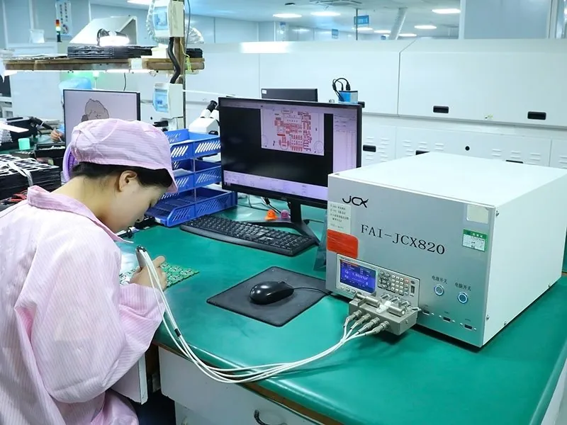
Verification of a rebuild explicitly checks all three: form — outline, mounting holes, connector positions measured against the original; fit — pinouts and interfaces confirmed net by net; function — behavior compared side by side with the original board, ideally in the target machine. Differences are documented and dispositioned, never waved through.
What to demand from any rebuild partner
Whether the rebuild happens with us or anyone else, the deliverable should include test evidence, not just boards:
- Inspection results (AOI/X-ray) for the assembled units
- Electrical test against the reconstructed netlist, not just a generic shorts-and-opens check
- A written functional test definition — what was tested and how it maps to the board's job
- Comparison data against the original board where one exists
- A first-article report before volume production
A partner who can't produce that list is asking you to do the verification yourself — in the field, on your equipment, on your schedule. The cost asymmetry is brutal: an hour on a test station versus a day of unplanned downtime. This is exactly the reasoning behind keeping testing inside the same team that did the reconstruction — the people who recovered the netlist are the people best positioned to audit against it.
The takeaway
Reverse engineering recovers a design. Testing proves the recovery. A board that has passed electrical test against its own reconstructed netlist, inspection under X-ray, and functional comparison with its original has earned the right to be installed. Anything less is a hope with a part number.
"Verification is the difference between a board that matches the original and a board that matches a drawing of the original."
Have a board that needs rebuilding — and proving? Tell us about it. We'll scope the reconstruction and the test plan together, so the "will it work" question is answered before the board ships.